
Challenge
Drilling a zone with losses can lead to poor cement quality or in severe cases a total absence of cement behind the casing resulting in free pipe. Cement quality and placement is essential to ensure optimal zonal isolation, minimize crossflow of corrosive fluids to prevent corrosion in the casing and subsequent potential leaks compromising the well integrity. Additionally, a poor cement job could result in high annulus pressures due to communication with higher pressure zones and exceed the maximum allowable annulus surface pressure (MAASP).
Acoustic Logging Result
One example when acoustic logging was conducted to identify crossflow behind casing is shown below:
The well was drilled in 2023. This deviated well was to be used as a relief well for a nearby well which had an integrity issue in the upper section of the well. This was not resolved by a Hoist intervention in 2021. The well history showed that the well had an integrity issue from 2008 when the 7” production liner was unsuccessfully pressure tested at 1107-1320 m. A pressure test of the 9 5/8” casing was not conducted, however a tapered 7” x 4.5” scab liner was run in hole to 1372 m. In 2011 the scab liner was cut and recovered from 1332 m. The remaining 4.5” scab liner from 1332-1372 m was left in place. A new tapered 7” by 4.5” scab liner was run in hole from surface to 1322 m. In 2013 both the C and B annulus leak-off tests (LOT’s) failed. In 2016 the completion string was pulled and a retrievable bridge plug (RBP) was run in hole and set at 417 m. A pressure test of the 7” scab liner was done in stages indicating an integrity issue at 273-418 m. A 7” scraper run tagged an obstruction at 283 m which was then milled out with a new HUD at 360 m. A cement plug was set with top of cement (TOC at 230) m and a 7” bridge plug set at 207 m. In 2021 the bridge plug and cement plug were milled out to 365 m and an EMDs corrosion log was run. Data from the log indicated that the 7” scab liner was parted at 206-226 m. In addition, the 7” scab liner, the 9 5/8” casing and the13 3/8” casing had severe corrosion from 290-324 m. A decision was made to isolate the upper section of the well and drill a relief well to intersect the existing well at a depth of 1325 m.
The relief well was drilled in Feb-Mar 2023 to 1325 m. The relief well was completed with 18 5/8” conductor (shoe@231.3 m), 13 3/8” surface casing (shoe@819 m), 9 5/8” intermediate liner (689-1419 m) and a 7” intermediate liner (1363.2-1531.7 m). The 7” liner was cemented.
Note, the acoustic logging was conducted under RIG-95 and the tool was run through the 13 3/8” casing, 9 5/8” liner and 7” liner.
Interpretation Summary
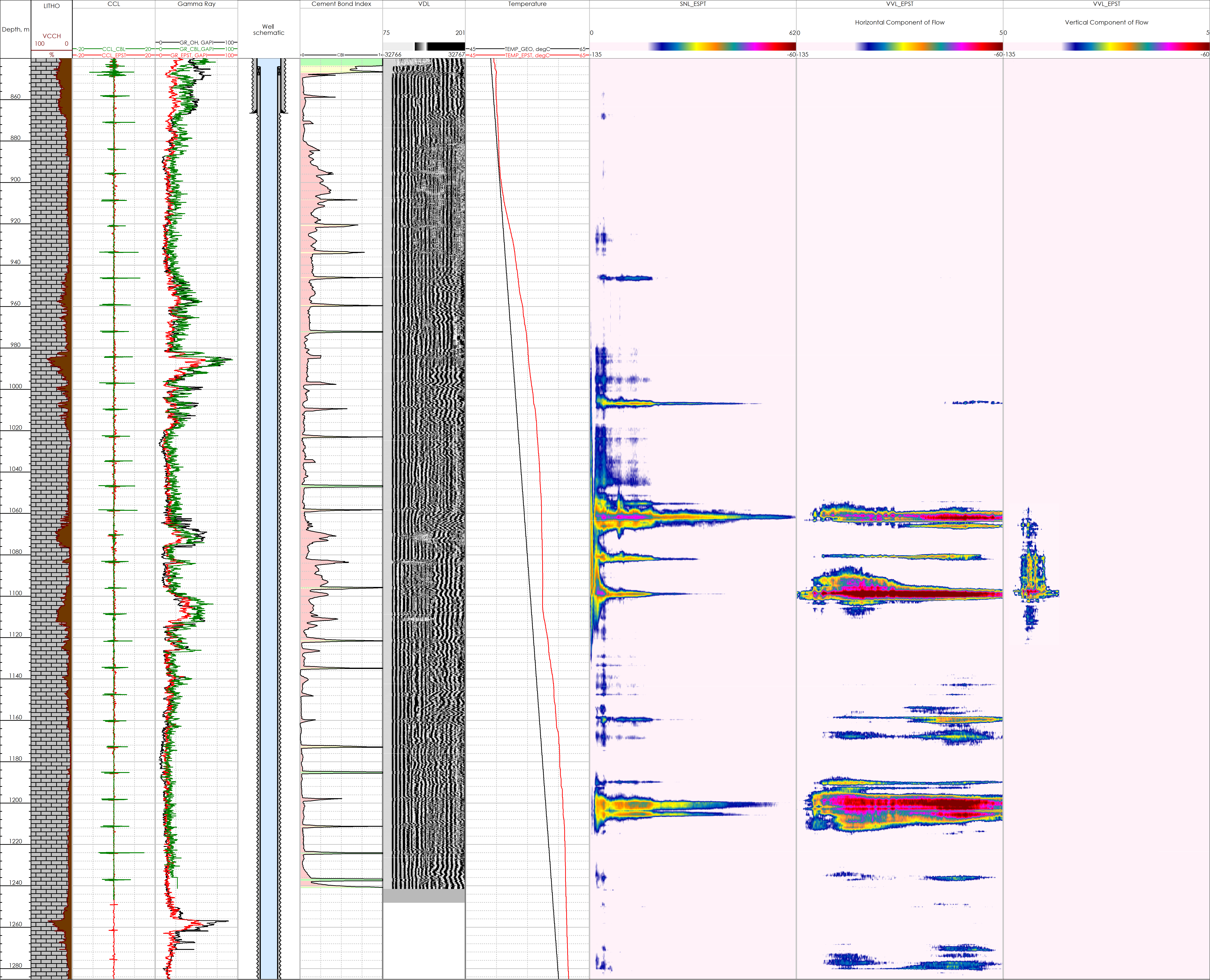
The main aim of acoustic logging in the relief well was to identify crossflow behind the 7” cemented liner as the liner was positioned across the interval where losses occurred during drilling. There is a history of natural crossflow in this formation.
The recorded SNL data and the horizontal component of flow from the VVL log indicated fluid movement from 980 -1280 m. This revealed the presence of a few narrow intervals with greater noise amplitude which, in all probability, could be associated with existence of a naturally fractured formation and lateral fluid movement. The vertical component of flow from the VVL log together with the temperature curve indicated the presence of crossflow from 1044-1103 m.
The CBL-VDL log run from 850-1240 m (top of the 7” liner) indicated poor cement quality across the entire logged interval with a very low cement bond index. This could be attributed to the CBL being run after 24 hours from cement placement instead of the recommended 72 hours to allow the cement to fully set.
However, the SNL+VVL were run 14 days after the cement job and the acoustic data had a good correlation with the cement bond index. The CBL showed a greater bond index at 850 -980 m and the SNL+VVL did not indicate crossflow behind the liner. Intervals with well-marked noise have the lowest cement bond index.
Conclusion
The combination of the SNL+VVL acoustic logging tool can identify sources of fluid movement and crossflow behind pipes. The data also validates the output from the CBL log.
All case studies


Looking for more information?
Get in touch with us and our representative will get back to you
Contact Us