
Challenge
Drilling through zones with total losses can lead to poor cement quality or in severe cases a total absence of cement behind the casing. This could lead to crossflow of corrosive fluids and ultimately corrosion in the casing and potential leaks.
Acoustic Logging Result
One example when acoustic logging was conducted was to identify the root cause of the B annulus leak-off test (LOT) failure, this is shown below:
The well is an S-shape gas lift oil producer drilled in 1992.
Drilling for 13 3/8” surface casing was to 525 m with total losses from a depth of 30 m. The 13 3/8” casing was run in hole with the shoe at 524 m. The casing was cemented in one stage with 45 m3 of slurry. Due to the total losses the top of cement was expected to be approximately 250-300 m.
Drilling continued to 1340 m where the 9 5/8” intermediate casing was installed (shoe@1165.00 m) and the 7” production liner was set at 1103-1316 m.
In December 2017, during a Hoist intervention a scab liner was run with the tapered tieback string (7”x5.5”x4.5”) at 854.82-1179.86 m. The existing 2.875” tubing was replaced with a new tapered 3.5”x 2.875” gas lift completion string (WEG@1181.17 m).
In September 2022 an integrity test (SIT) was conducted, the B annulus leak-off test (LOT) failed (unable to build up pressure) and the A annulus inflow test failed.
Interpretation Summary
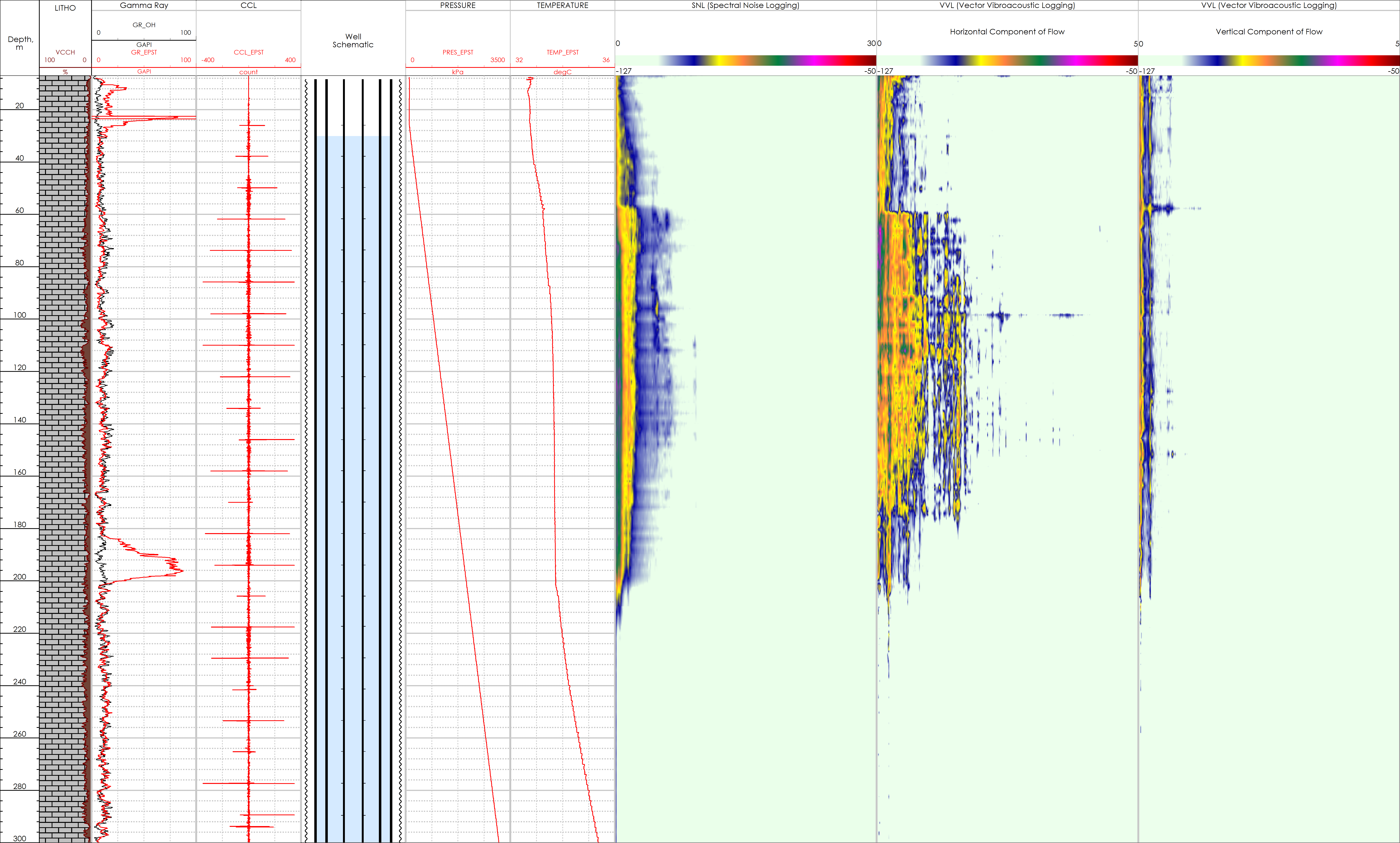
An acoustic logging pass was conducted while pumping water into the A annulus. SNL data showed fluid movement from surface-200 m. VVL data indicated the presence of vertical downward flow movement at an interval from surface-200 m. It was observed that the formation was taking fluid flow horizontally from 56-200 m with a more intense flow at 56-74 m. The temperature curve supported the acoustic log findings as the temperature curve confirmed crossflow at 60-200 m. The gamma ray curve showed significantly greater counts at a depth of 23 m compared to the original open hole log. This could be attributed to scale accumulation (possible depth of leak on the 9 5/8” casing and 13 3/8” casing). Additionally, the gamma ray curve had greater counts from 183-200 m which confirmed the end of the crossflow zone.
Considering the drilling history (losses across the upper section) and the acoustic log results, the main conclusion of this survey is that:
The 9 5/8” casing has a through-wall defect at a very shallow section at 23 m. The water pumped into the A annulus passed through the leak in the 9 5/8” casing and into the B annulus. The fluid then entered the formation and travelled to a depth 200 m. The flow across the formation was not even with a different intensity across the interval 56-200 m.
Conclusion
In the event of a failed LOT test, an acoustic log can be run which to identify the depth of a leak and determine any fluid movement behind the pipe. Combining corrosion and acoustic logging gives a more complete picture of the overall well integrity status.
All case studies


Looking for more information?
Get in touch with us and our representative will get back to you
Contact Us